
The liftoplane can be used with an enlarged wingspan to have a higher aspect ratio, and therefore the performance reflected in the LDR, due to decreasing of inflow. But, that cannot be performed straightforwardly, simply by installing more longer wings on each rotor, since they wouldn't possess the enough rigidness against the loads from the aerodynamic and centrifugal forces. So, there needs some intermediate ring for that.

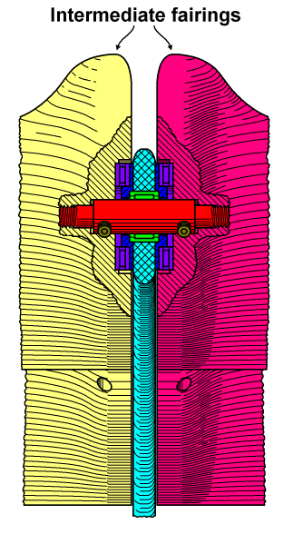
An option of using the rotor with an intermediate ring in its middle is represented in the chart above. In this option, instead of each one wing, two wings are used: the inner wing of the pink color and the outer wing of the light yellow color. These wings have generally the same length. Also, the most distanced ends of these wings have exactly the same fairings as the original wing. The outer end of the inner wing and the inner end of the outer wing have symmetrically equal intermediate fairings, which provide enough space for the elements linking these wings to each other. An intermediate ring of the cyan color has flat surfaces on both sides. It is made of composite material and has equidistant holes related to the corresponding wings. A radial needle bearing of the green color is inserted into each such a hole of the intermediate ring. Adapter flanges of the blue color are dressed on the radial needle bearing on each side. The intermediate fairings of the respective wings have flat intermediate bases adjusted to the respective sides of the intermediate ring. And from these directions, they have interior spaces used for their rotational mating with the adapter flanges, with thrust bearings of the violet color lying on these adapter flanges. A link shaft of the red color is inserted into the radial needle bearing, thrust bearings, adapter flanges and into two respective intermediate fairings, where it is screwed into corresponding threaded holes by its threaded tails. The inner tail has a right handed thread, and the outer tail has a left handed thread. Two set screws of the dark yellow color on each side of the intermediate ring fix the shaft against unscrewing, using some setup holes on both sides of the intermediate fairings.
During the setup of the intermediate ring and the outer wings, those set screws can be periodically screwed and unscrewed on respective sides to switch between the screwing of the shaft or the outer wings relative to the stationary inner wings. So, for this operation, the outer wing acts as some handle, and only one from two set screws can be used for this kind of switching. And, the operation will be completed when the overall gap of the bearings will be optimal, having a free rotation without a backlash with coinciding of the trailing edges of the inner wing and the outer wing. After this, all four set screws should be fixed. The high diameter of the shaft with using these set screws permits to transmit enough high torque from the inner wing to the outer wing. This kind of assembly of the intermediate ring together with the outer wings on the inner wings permits their fast installation after the first setup. Indeed, in the case of a disassembling, only from one side these set screws can be unscrewed. So, for the next installation, each outer wing will be screwed together with its constantly assigned inner wing, simply by its rotating, until their trailing edges will be coincided without a visible backlash in their linking. Also, the rotor may be extended to use more than one intermediate ring.
Copyright © 2018-2023 Yuri Feldman - All Rights Reserved