

The steering solution of the rotors of the liftoplane is based on a four-gears pitch steering scheme. The kinematic scheme of such a rotor is represented below and follows with an explanation.
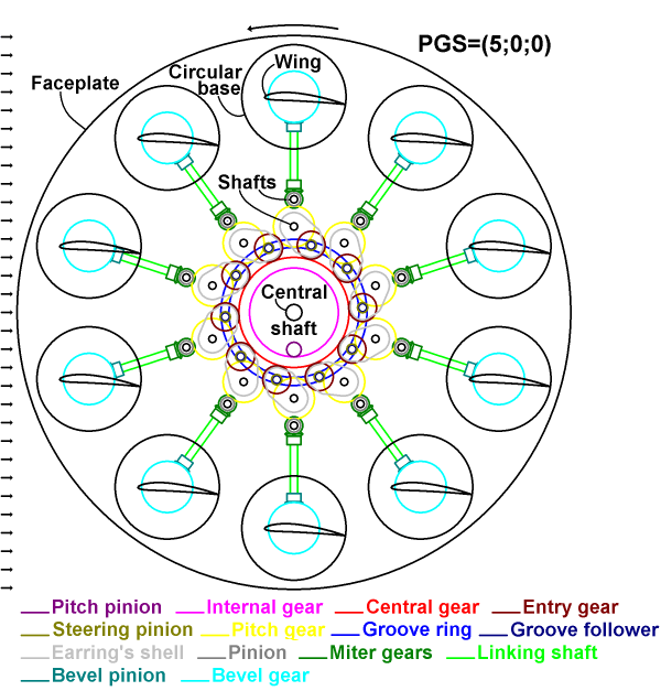
The scheme is performed in such a way that indicates the actual clearance of neighbored pieces and ensures that no collisions occur. The view should be understood as a transparent projection of the depicted selected internal elements onto the faceplate of the rotor. Any intersections of the selected elements in the scheme mean an overlapping those elements in separate plans. The picture represents the rotor in a neutral pitching with PGS=(5;0;0) relative to the base airflow and with the indicated rotation direction that is appropriate for the particular pitching. The rotor has a faceplate on which some elements are mounted that support the shafts of the wings, those elements and the shafts of the wings aren't pictured on the scheme. The wing has a circular base, which is an integral part of the wing. A bevel gear of a large diameter is mounted on the circular base. A bevel pinion is meshed with the bevel gear and mounted on a linking shaft. The other end of the linking shaft has a miter gear, which is meshed with another miter gear, which is joined in a cluster with a pinion and is fixed on a respective shaft. This pinion is meshed with a pitch gear fixed on another respective shaft. Also a steering pinion is meshed with the pitch gear and is joined in a cluster with an entry gear. A groove follower is mounted on the latter cluster and can move inside of a groove ring. The pitch gear with its shaft, the steering gear, the entry gear and the groove follower are assembled as an earring inside of an earring’s shell, which can hold a number of supporting bearings. A central gear is meshed with the entry gears of all the earring assemblies and is clustered with the groove ring and with an internal gear. A pitch pinion is meshed with the internal gear. A central shaft is fixedly connected to the faceplate and is used for powering the rotor.
The cluster of the central gear together with the pitch pinion can move in any radial direction up to a certain limit, changing the Gain and Skew of the entire PGS-state. Each earring’s shell has a some "window" for the pitch gear of the neighboring earring assembly, preventing collisions during steering. The pitch gear has its name because it always is synchronized in rotation with the related wing. The pitch pinion has its name because its rotation will change the Pitch of the entire PGS-state. The steering pinion has its name because it directly steers the pitch gear. The entry gear has its name because it acts as an entry interface for the entire earring assembly. The pitch gear, the central gear, the entry gear and the steering pinion are the base elements of the four-gears pitch steering scheme.
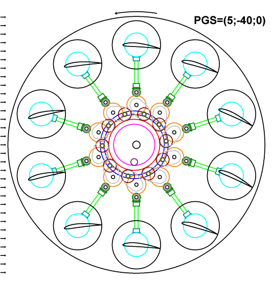
The chart above represents the same kinematic scheme as before, but the rotor is in a high negative gain pitching with PGS=(5;-40;0), which can be used upon gaining altitude. The scheme demonstrates how the pitches of the wings and the positions of the earring assemblies will change upon moving the entire cluster with the central gear together with the pitch pinion for this pitching. In this high gain pitching there is still sufficient clearance between the earring assemblies, and the applied movement of the entire cluster is far from maximal.
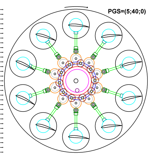
The chart above represents the same kinematic scheme as before, but the rotor is in a high positive gain pitching with PGS=(5;40;0), which can be used in recuperative descent. The scheme demonstrates how the pitches of the wings and the positions of the earring assemblies will change upon moving entire cluster with the central gear together with the pitch pinion for this pitching. The remained clearance here is same as in the previous case. Also, the indicated direction of rotation of the entire rotor is opposite, since this pitching is related to recuperative descent.
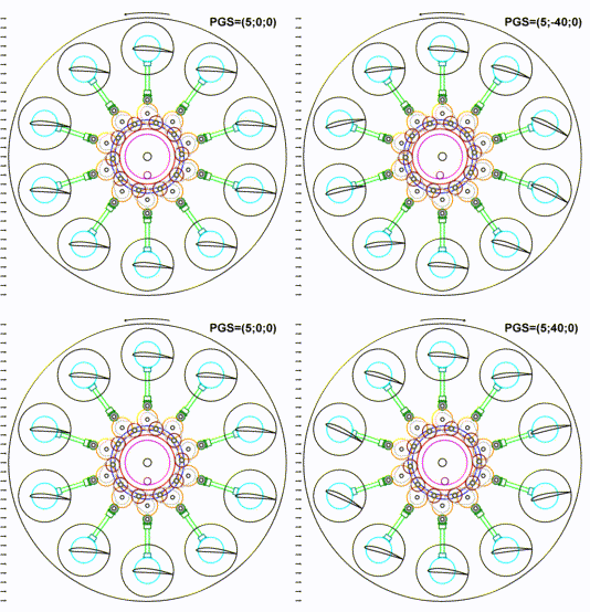
The animation above represents a comparative view for changing of the rotor wings pitching over all three PGS-states presented before.
It will be very useful to have an end use formula for obtaining the pitch variation of particular wings upon moving the central gear in the four-gears pitch steering scheme. This variation will be a function of the instant distance between the axis of the pitch gear and the axis of the central gear. And this variation will be independent of an orthogonal offset of the central gear from the center of the rotor for this fixed distance. The latter feature may be intuitive, but it isn't obvious. However, it can be proved by the following analysis.
Let the central gear move orthogonally from some pitch gear, but their distance will be kept. This movement can be considered as a turn of all four gears participated in the steering, by some angle, with a frozen meshing state. In such a case, the pitch gear will obtain an additional variation, which is equal to the angle of rotation of the system of these four gears. But in this case, the central gear also should obtain the same additional variance as the pitch gear because the meshing state is frozen. But actually, the central gear is fixed from any rotation with the pitch pinion that is irrotational for this movement. And so, the pitch pinion will imply a counteraction that returns this central gear in its original angular position. This reverse rotation of the central gear will break the frozen meshing state of four gears, and the pitch gear will also return to its original angular position, because all pitch gears are synchronized with the central gear in their collective angular movement by the equality ratio.
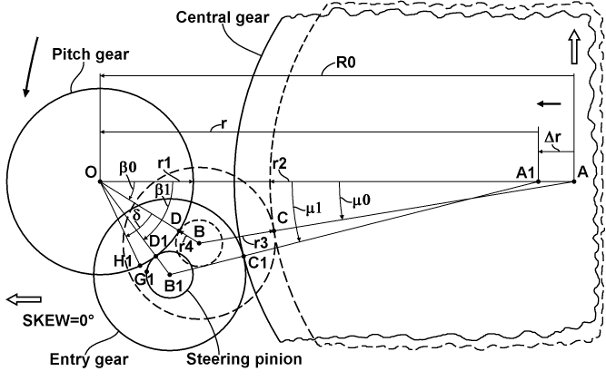
The chart above explains movement all gears relative to some pitch gear upon changing its distance from the central gear. The chart pictures the pitch gear in a horizontal position and upon a zero-Skew pitching of the rotor, but this is not principally for the result that will be obtained. At first, all participating gears have corresponding radii based on their pitch diameters. The pitch gear has a radius r1, the central gear has a radius r2, the entry gear has a radius r3, and the steering pinion has a radius r4. At second, there is a radius of the circle on which the axes of all pitch gears lie. It is designated as R0. At third, a triangle can be constructed with corners based on the axes of the pitch gear, the central gear and the cluster of the entry gear and steering pinion. In this triangle, the axis of the pitch gear is fixed relative to horizontal offset, so, it is designated by the letter O. The axis of the central gear in the neutral position is designated by the letter A, and the axis of the cluster is designated by the letter B for this case. In the case of an offset Δr, last two points will be A1 and B1, respectively. Also, for the triangle OAB, two corner angles for points O and A can be assigned as β0 and μ0, respectively. And for the shift case, they will be designated as β1 and μ1, respectively. Additionally, two meshing points can be considered: between the central gear and the entry gear as the letter C, and between the pitch gear and the steering pinion as the letter D. Also, for the shift case, they will be designated as C1 and D1, respectively. And finally, the pitch variation of the pitch gear upon the shift of the central gear can be designated as δ, and it will be correspond to a reposition of the original meshing point D. The point D will be reposed to two instances. One the instance will lie on the pitch gear and is designated as H1, and the other will lie on the steering pinion and is designated as G1.
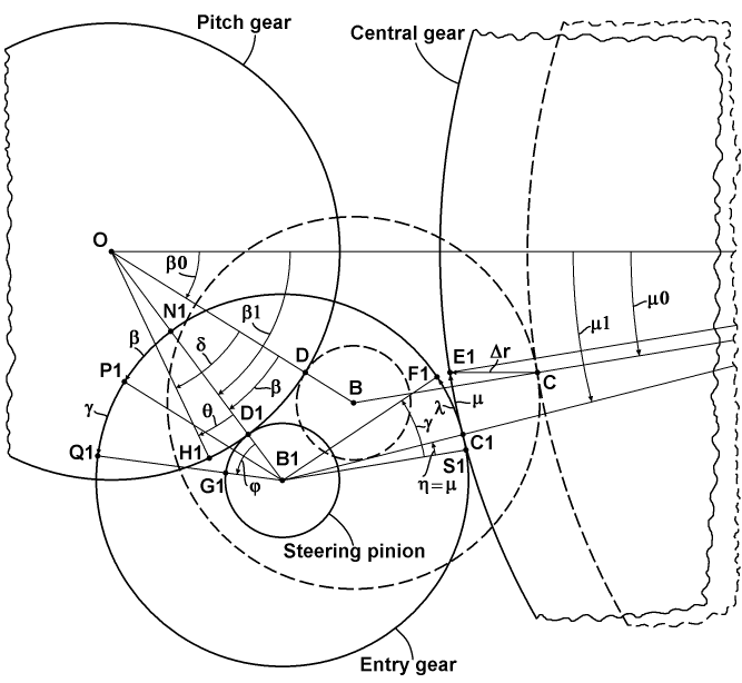
The chart above represents a magnified essential portion of the previous chart with additional details for deducing the target variation formula. At first, there is presented a reposition of the original meshing point C to two points E1 and F1 laid on the central gear and the entry gear, respectively. Here, E1 is simply the result of the offset the point C by the vector Δr. The changing from the angle β0 to β1 upon the offsetting corresponds to the changing in the related meshing position, and so, the angle of this change is designated as β. Also, an angle μ of the same kind is designated for the other meshing position. And so, the target angle δ can be considered as the sum of the angular change β of the meshing position and a remainder θ that is equal to an additional rotation imposed by the steering pinion itself. The angle θ has a corresponding angle φ on the steering pinion, related to it by a simple gear ratio. This angle φ can be decomposed as the sum of the common change β of the meshing position and an angle γ representing a rotation of the entire cluster. Here, the angle β is secondary pictured as an arc between the points N1 and P1 on the circle of the entry gear, where B1P1 is parallel to the OB and N1 is simply a crossing of OB1 with the circle of the entry gear. Also, the angle γ is pictured on the circle as an arc between the points P1 and Q1, where the latter is a projection of the point G1. The angle γ can be expressed as the sum of an angle η representing a change of the meshing position of the entry gear, and a remainder λ. The angle η is equal to the μ and is pictured as an arc on the circle of the entry gear between the points S1 and C1, where B1S1 is parallel to the AB. The remainder λ is related to the μ by a simple gear ratio. So, now all the components to deducing the target formula exist.
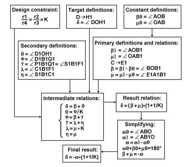
The diagram above represents the entire process of deducing the target formula by grouping the subjects of this deducing. At first, there is one design constraint for the equality of both of the gear ratios to a certain value K. At second, there are target definitions for the reposition of the primary meshing point on the pitch gear and for the angle of variation itself. At third, there are two constant definitions for the base angles in the neutral case. Fourth, there are primary definitions and relations for a particular position of the pitch gear in the case of shift, including: base angles, a reposition of the primary meshing point on the central gear, and simple equations for variations of those base angles. Fifth, there are secondary definitions, including: the first remainder and its corresponding angle, the angular variation of the cluster, and the second remainder with the related angular change of the second meshing position. All these five subjects merge together and lead to intermediate relations, which are resolved by simple algebra to one result relation. This result is passed to a simplifying based on the constant sum of angles in a triangle, providing by that the final result, which states: the pitch variation is equal to the product of inversion of the variation of the apex angle and the sum of unity and the reciprocal of the common gear ratio, where the gear ratio is defined as the ratio of the radius of the central gear to the radius of the entry gear.
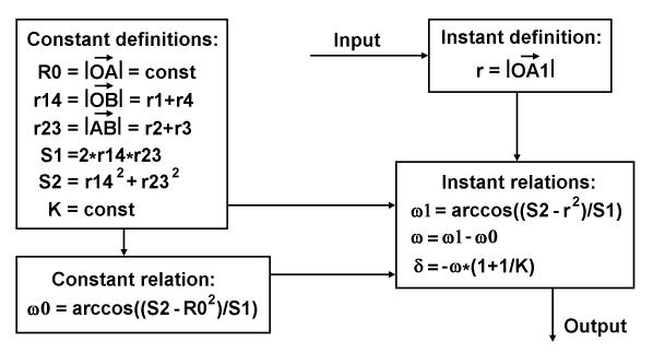
The diagram above represents a data flow with definitions for an end-use application of the pitch variation formula for a particular distance of the pitch gear from the central gear. At first, the application routine must be initialized with the values of the constant definitions. At second, this initialization must be continued by calculating the constant relation, which is based on the cosine theorem and provides the value of the apex angle in the neutral case. After it, the routine can acquire input of a particular angular position of a wing, which is equal to the angular position of its pitch gear, and calculate an instant distance, using the instant definition. After this, the routine should substitute the values from all the mentioned subjects into the chain of the instant relations and calculate the final value of the variation, for the output.
The plot below represents a particular result of using the pitch variation formula as the distribution of pitch deviation over all wings' positions of the rotor.
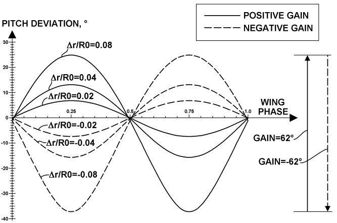
The result is represented in a wide set of central gear radial offsets for positive and negative gains. The sign of the Δr value is used to display the gain on such a way to be same as the sign of this gain itself. So, its ratio to R0 is used there as a gain parameter, which can be called a linear gain. This result corresponds to the placement of the four gears pictured in the gears geometry chart, which I call a normal assembling. But, the kinematic scheme represented before utilizes another placement variant, which I call an inverted assembling. A corresponding result of the distribution of pitch deviation over all positions of the rotor wings for the inverted assembling is shown in the plot below.
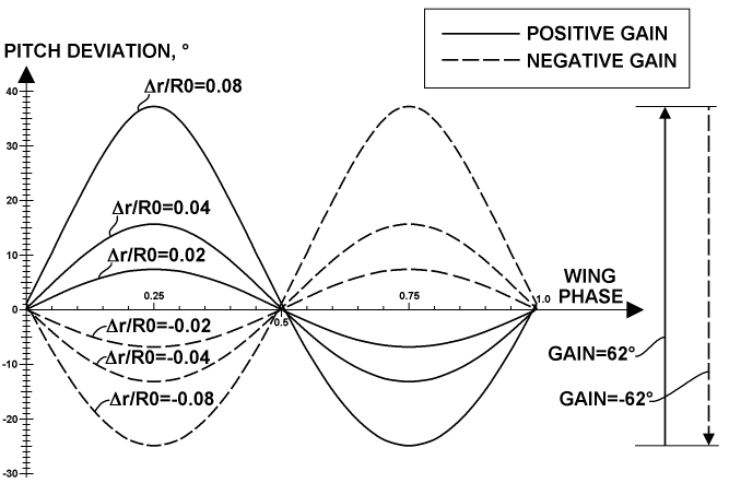
There, the sign of Δr was changed to be same as the gain sign. This result reflects some advantage of the inverted assembling variant: the main operating modes utilize the negative gain and have heavily loaded wings near the main point, which is near the phase 0.25, so, these wings have a lower pitch deviation upon using the inverted assembling, which provides more exact handling and steering of these wings.
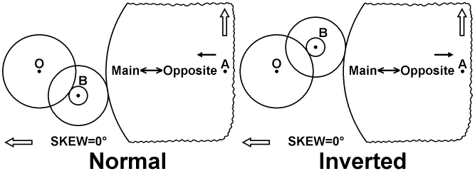
The chart above represents features of both normal and inverted assembling, respectively, by a comparative way. In the latter case, the entry gear with the steering pinion is placed in the upper elongation relative to the pitch gear and the central gear, on the side of the zero-Skew direction. Also, the positive direction of the linear gain is referenced on both charts as the black arrow above the Main<―>Opposite indicator for this zero-Skew pitching.
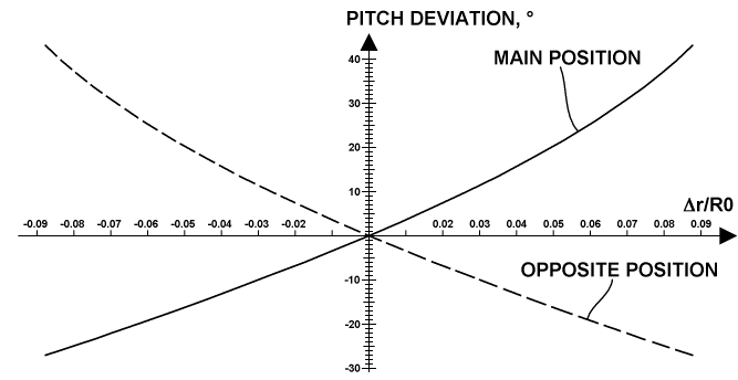
Of special interest is the behavior of the pitch change in the main and opposite positions when changing the linear gain in its entire range. A result of this kind of calculation is represented in the plot below.
Also, it may be interesting the changing of the angular gain itself when changing the linear gain in its entire range. A result of this kind of calculation is represented in the plot below.
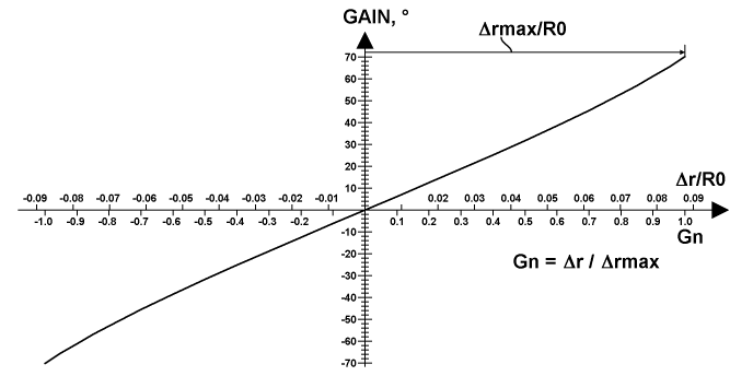
This plot also introduces a Normalized Linear Gain (NLG, Gn), which is equal to the ratio of the linear gain to some maximal linear gain related to a maximal constructive limit in the offset of the central gear, or simply equal to the ratio of the current offset to its limit. The latter definition is pictured in the plot below an alternative scale based on the linear normalized gain. This normalized gain variant is very useful for indicating a gain when using a mechanical indicator, since the mechanics are much simpler and more accurate when measuring linear displacement.
Copyright © 2018-2023 Yuri Feldman - All Rights Reserved