
The next aerodynamic aspect is related to induced drag. For airplanes, it is routine practice to use special formulas to calculate induced drag and the related correction of lift for a given aspect ratio. Such formulas reflect changes in drag and lift created by the influence of the inflow depending on the lift distribution over the wings. But this practice isn't applicable for modeling the powered actuators, like the presented rotor or the rotor of a helicopter, because its modeling implies to know a particular lift and drag of each particular wing of such a rotor. And the simple application of the mentioned formulas to each separate wing isn't correct, due to the mutual influence of the wings. This problem can simply be resolved with the knowledge of the inflow itself. And so, the next aerodynamic aspect for the presented rotor is the calculation of the entire inflow.
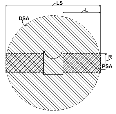
The inflow has a simple relation to the thrust specific area (TSA) of an actuator. From the lifting line theory and from the point of view of the momentum theory of actuators is known: for a monoplane with elliptically loaded wings in the wingspan direction, the TSA is simply an area of the circle based on the wingspan diameter. But the aircraft with the presented rotor doesn't have this elliptical load distribution. Presumably, it has an equal load distribution. This kind of distribution is also often used for monoplane modeling, and it implies a certain coefficient of efficiency that reflects an additional increasing of the induced drag due to a variable distribution of the induced speed, and which is practically above 0.85. But the aircraft with the presented rotor from the glider's point of view isn't a monoplane. For most flight operations, it can be considered as a tetra-plane with an average wings' separation of about 0.05 to 0.07 of its wingspan, or as a bit less-performing triplane with an average wings' separation of about 0.075 to 0.1 of its wingspan. From the work of L. Prandtl "Induced drag of multiplanes", published in NACA TN 182, 1924, one can easily find a coefficient of induced drag of this triplane over an equivalent monoplane. It lies between 0.852 and 0.824 for this referenced range of the wings' separation, respectively. This decrease in induced drag will overlap that increase due to non-elliptical load. So, as a pessimistic appreciation, it can be assumed that the induced drag of the aircraft with the presented rotor is equal to the induced drag of an elliptically loaded equivalent monoplane. And so, going from induced drag to inflow, the TSA of the aircraft with the presented rotor in the case of a gliding will be a circular area based on the wingspan LS, as shown in the chart below.

I call this area a downwash specific area (DSA), since it has a direct logical connection to the downwash feature. The impact from the cross-sectional projection of the fuselage will slightly decrease the DSA, but from the other side, it will slightly increase the wings' separation of the equivalent triplane, so I neglected this effect. The aircraft with the rotor presented also exhibits another kind of TSA: this is a propulsion specific area (PSA), which is actualized at the beginning of acceleration on the runway. I selected this area as the sum of the cross-areas of two cylinders based on both rotors with a radius R equal to the distance of the pivot axes of the wings from the center of the rotors, and a length L for each.
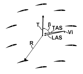
Another parameter that is necessary for calculating the inflow is the thrust specific angle, which is denoted as β. The chart below explains its relationship with thrust and airspeed.

The inflow modifies the TAS to the common LAS of the rotor. And this LAS has some angle relative to the thrust vector T. It is the β angle. It affects the inflow as follows: when the β is zero, the rotors perform as a pure propeller with TSA equal to PSA, and when the β is 90°, the rotors perform as a pure glider with TSA equal to DSA. In any intermediate case, TSA can be calculated using a simple quadrature formula based on these orthogonal components and angle β. Interestingly, for a helicopter, both areas of the PSA and DSA are equal when the PSA is considered to hover, so the helicopter practically has a constant TSA.

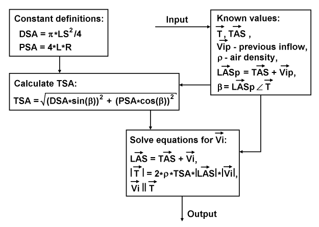
The diagram above represents the data flow and definitions for calculating the inflow. At first, there are constant definitions for DSA and PSA. At second, there is an input of known values, including: thrust vector T, TAS vector, previous vector of inflow Vip, air density ρ, chain calculated value of the previous LAS vector (LASp), and β angle. The process continues by calculating the TSA using the presented quadrature formula that utilizes DSA, PSA and β. The resulted TSA enters together with the TAS and thrust vectors into a routine to solve equations based on the desired inflow vector Vi. These equations consist of: an equation for the presumed total flow LAS; a scalar equation reflecting the moment conservation law, and based on the presumed total mass flow and the magnitude of the unknown inflow; and a relation used to restore the entire inflow vector. This routine resolves the first two equations together using Newton's iterative method, and restores the entire inflow vector for output.
Copyright © 2018-2023 Yuri Feldman - All Rights Reserved